As the global stone industry evolves, a modern stone fabrication shop is no longer defined by manpower alone, but by automation level, processing accuracy, production efficiency, and equipment integration. Whether you are fabricating granite, marble, quartz, or sintered stone, choosing the right machines directly determines your product quality, delivery speed, and long-term profitability.
Based on real factory applications, customer feedback, and international market trends, below are the 5 essential machines every modern stone fabrication shop needs, along with practical usage scenarios, technical comparisons, and buyer-focused insights.
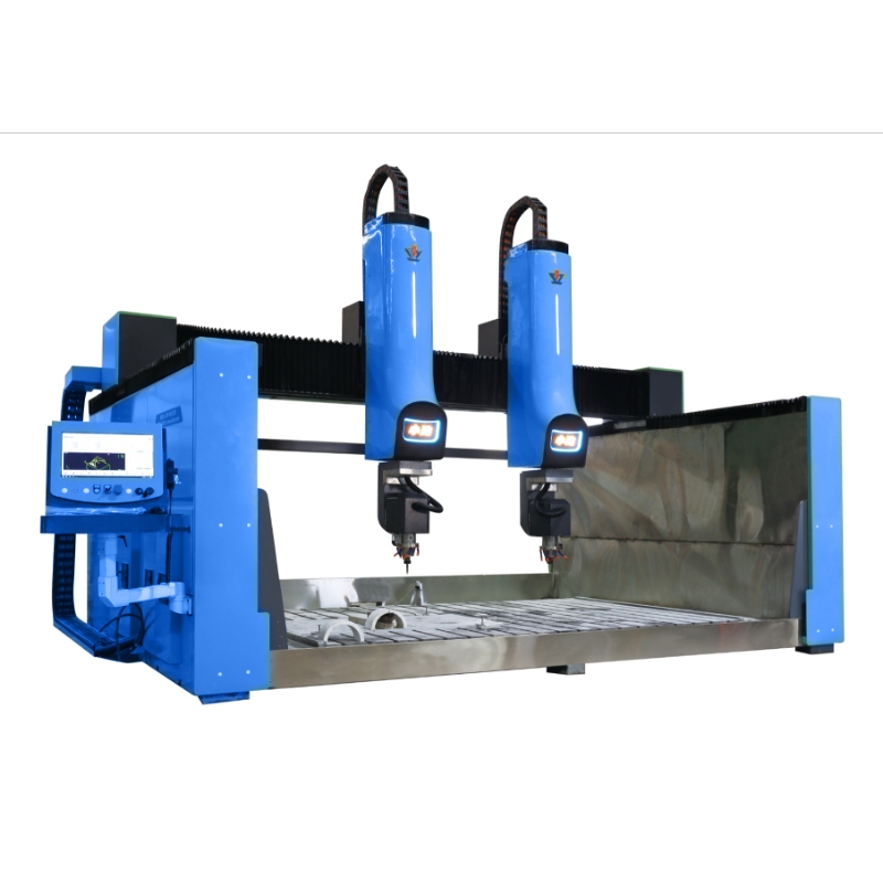
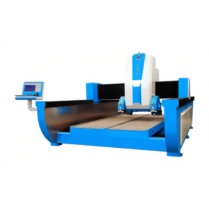
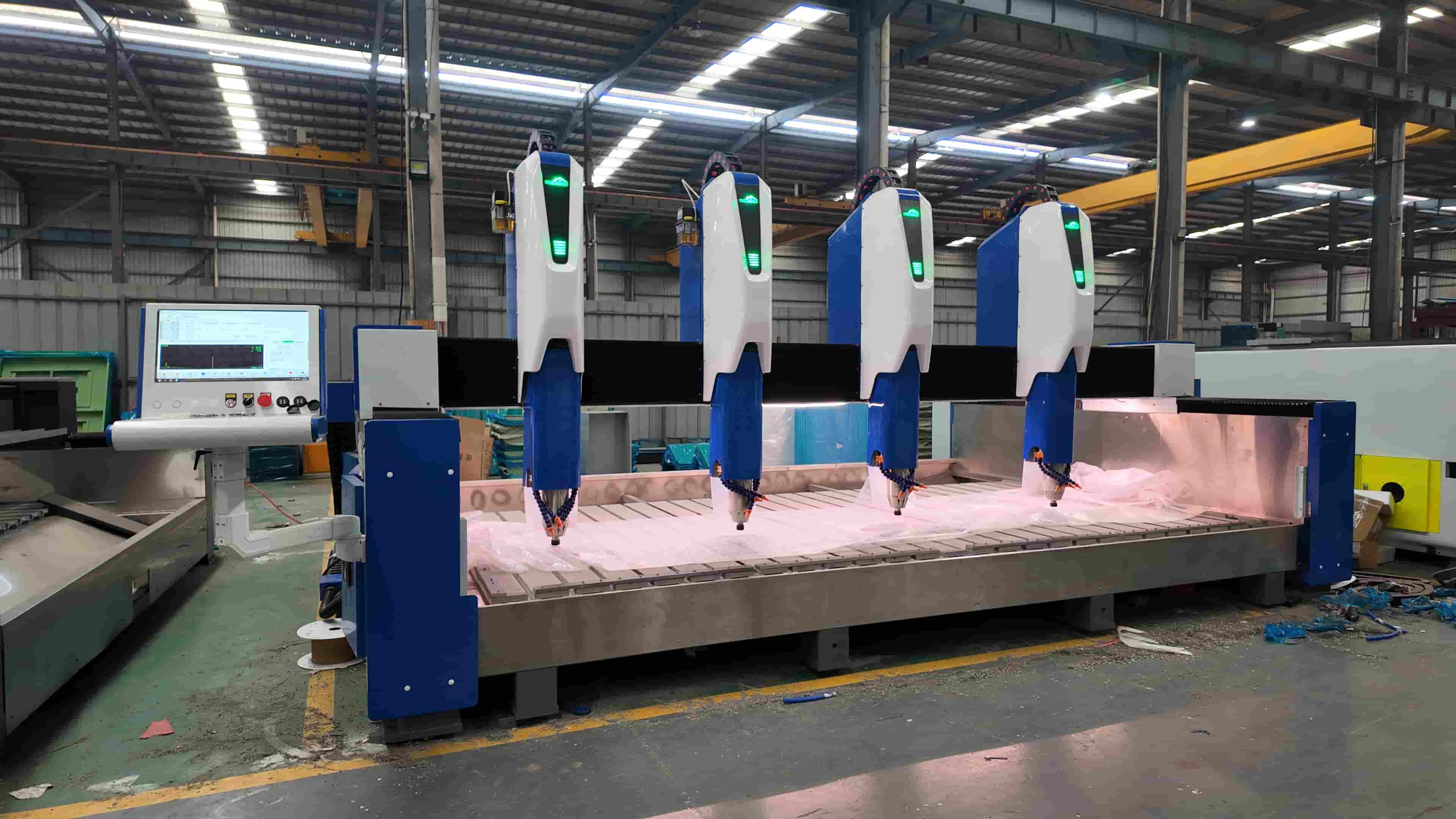
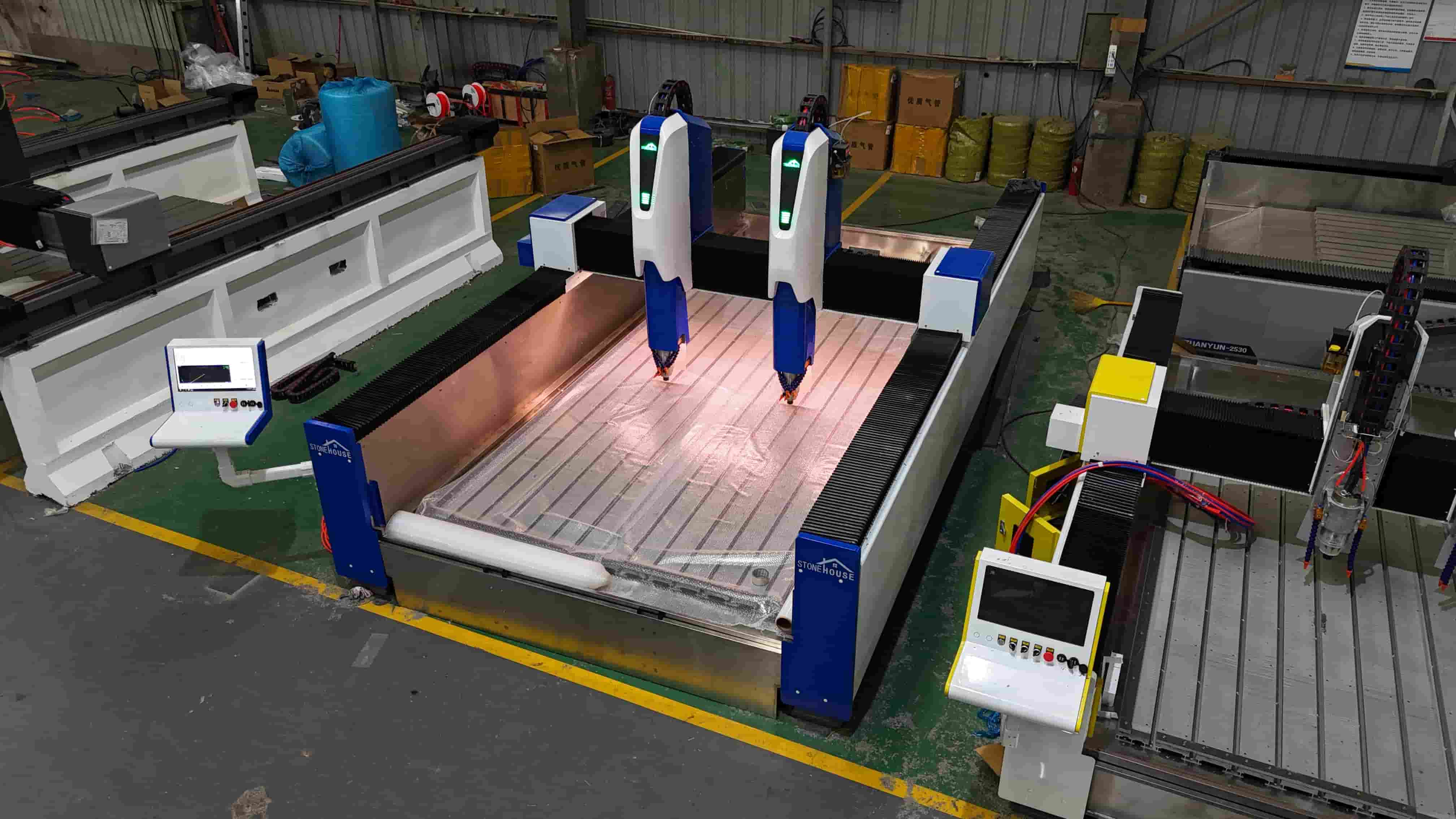
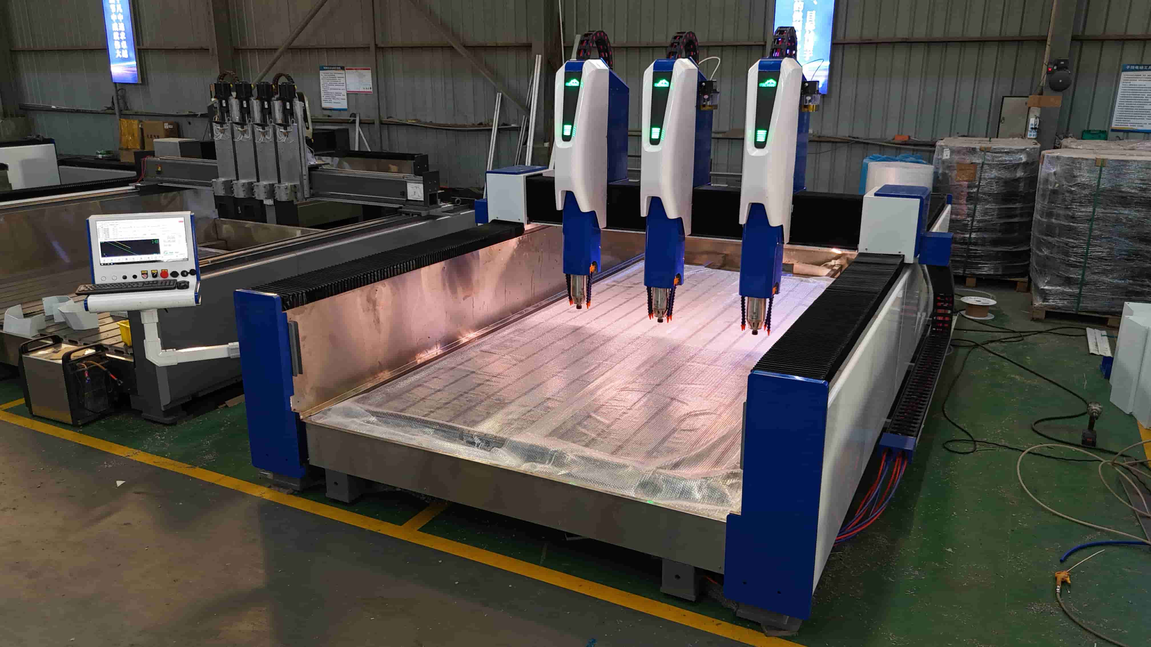
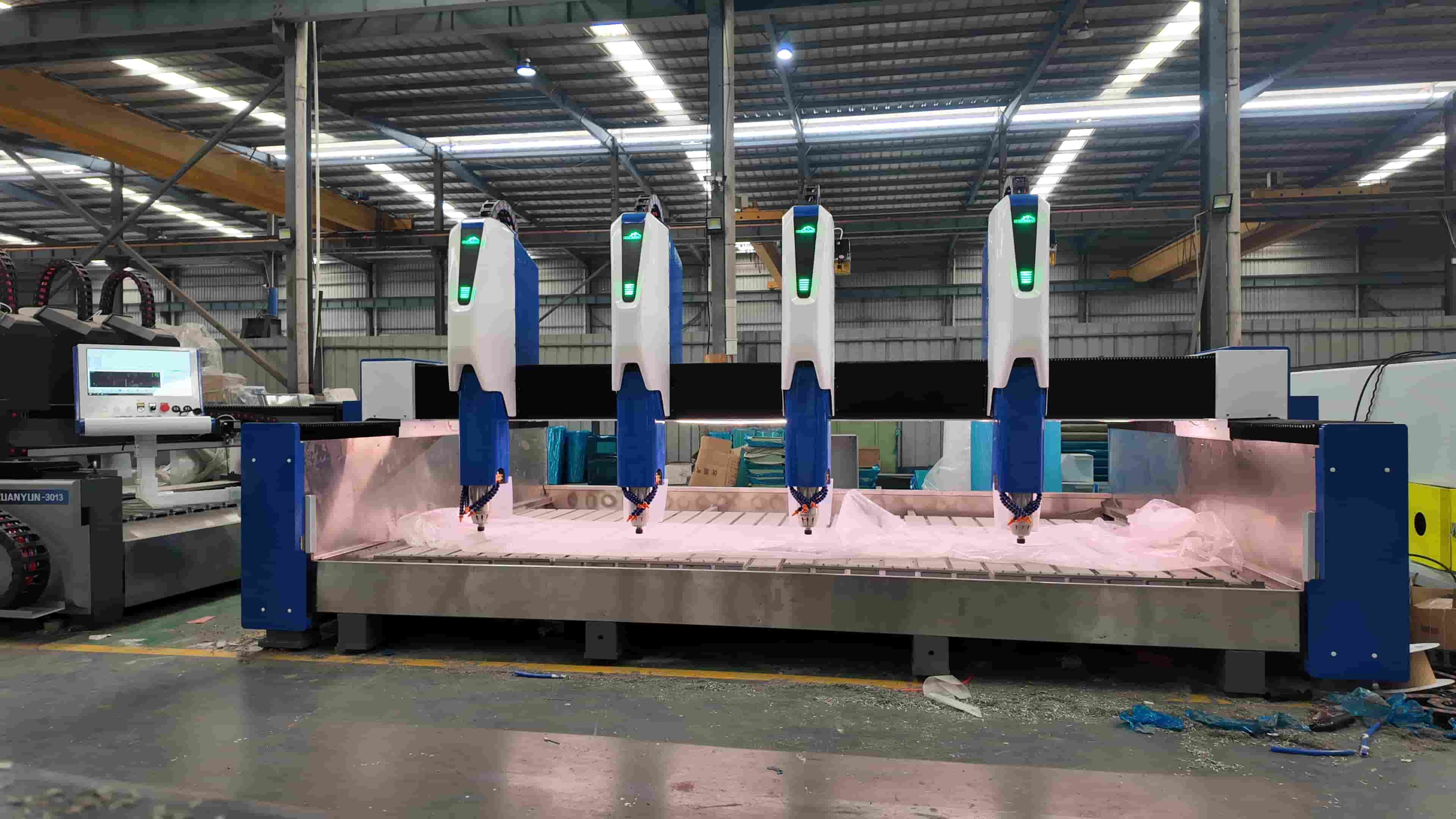
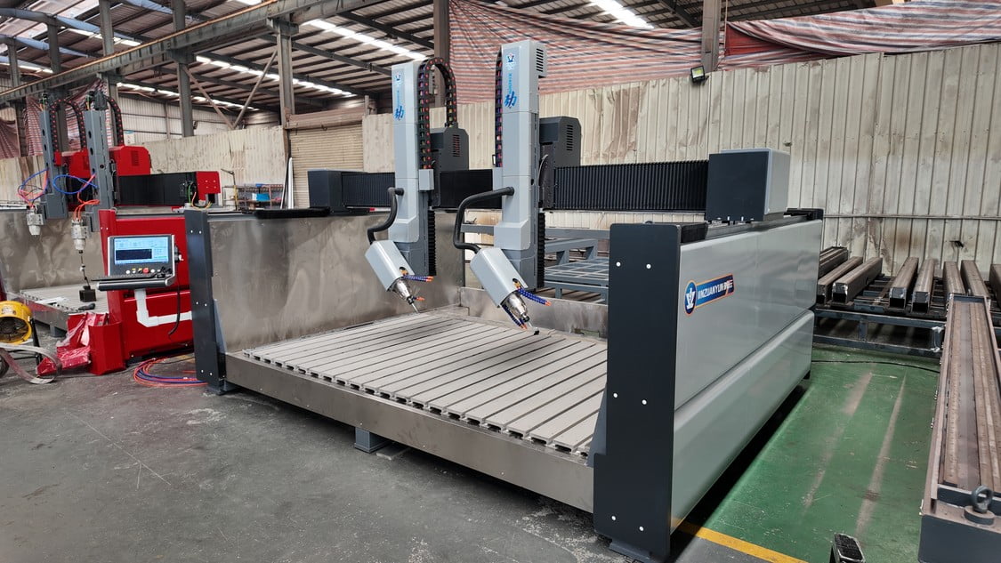
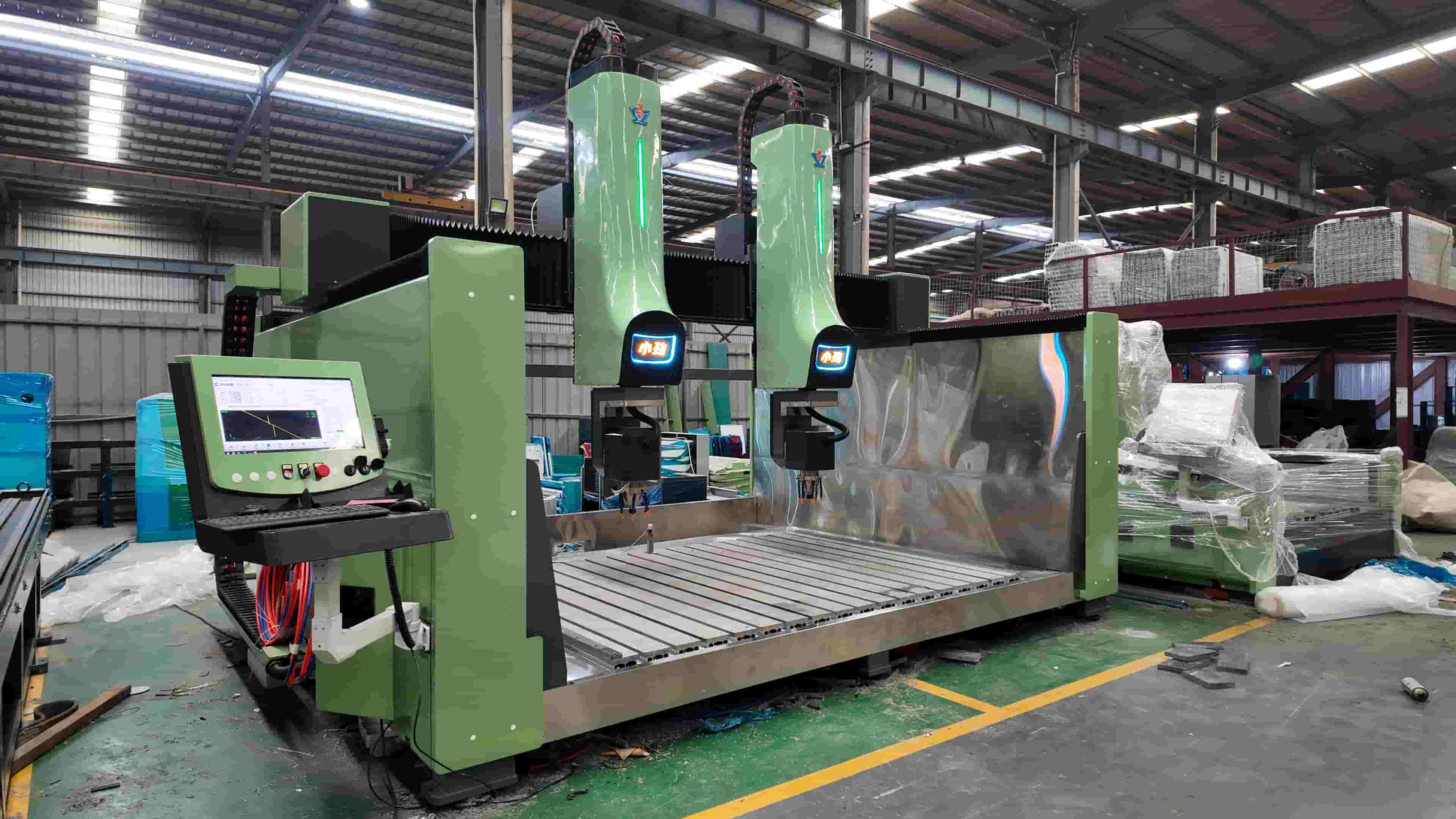
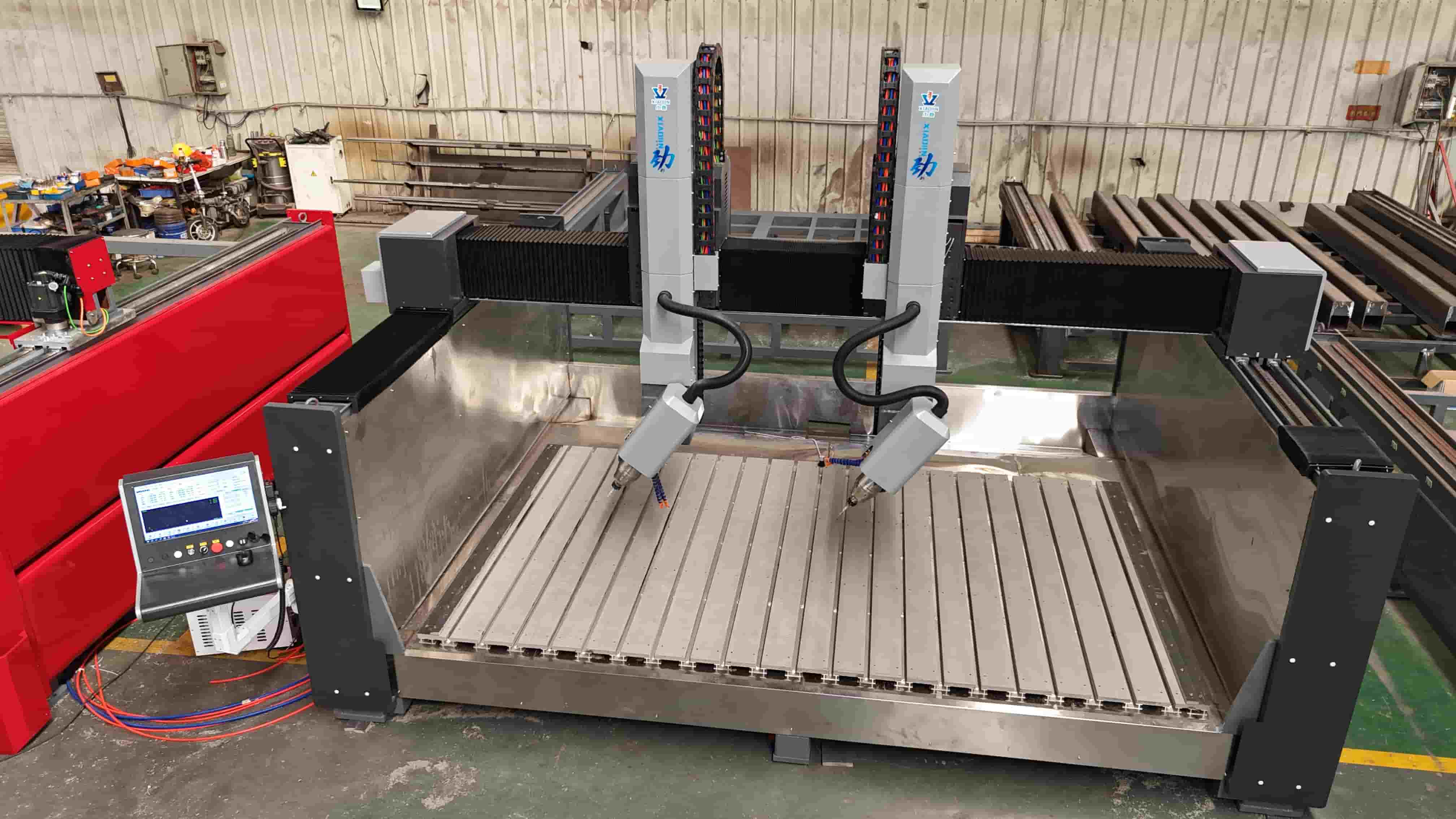
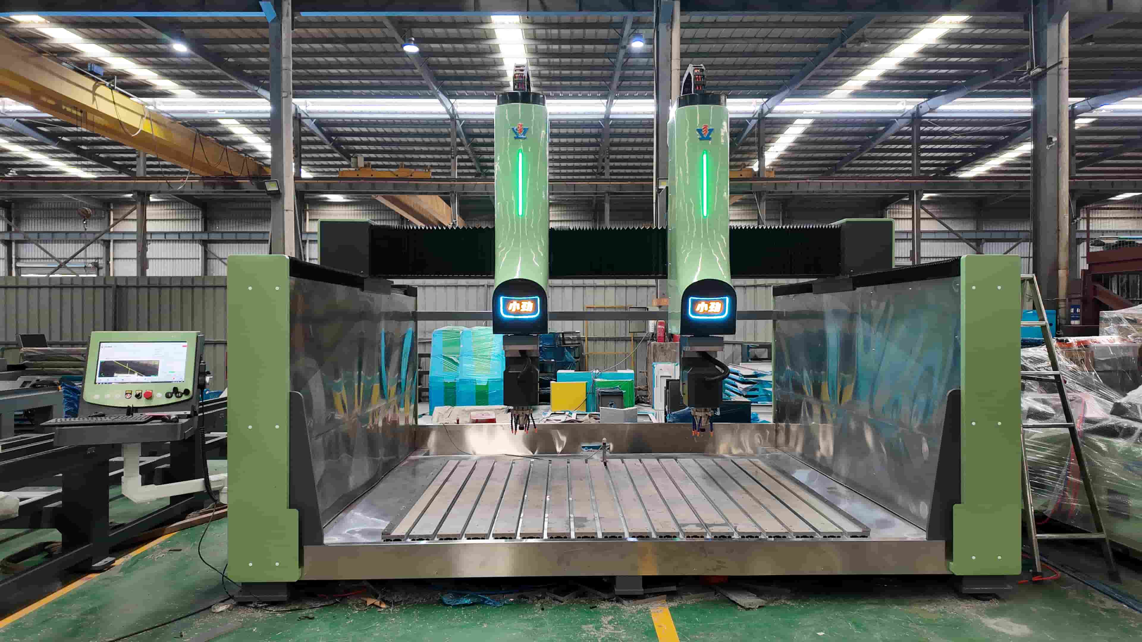
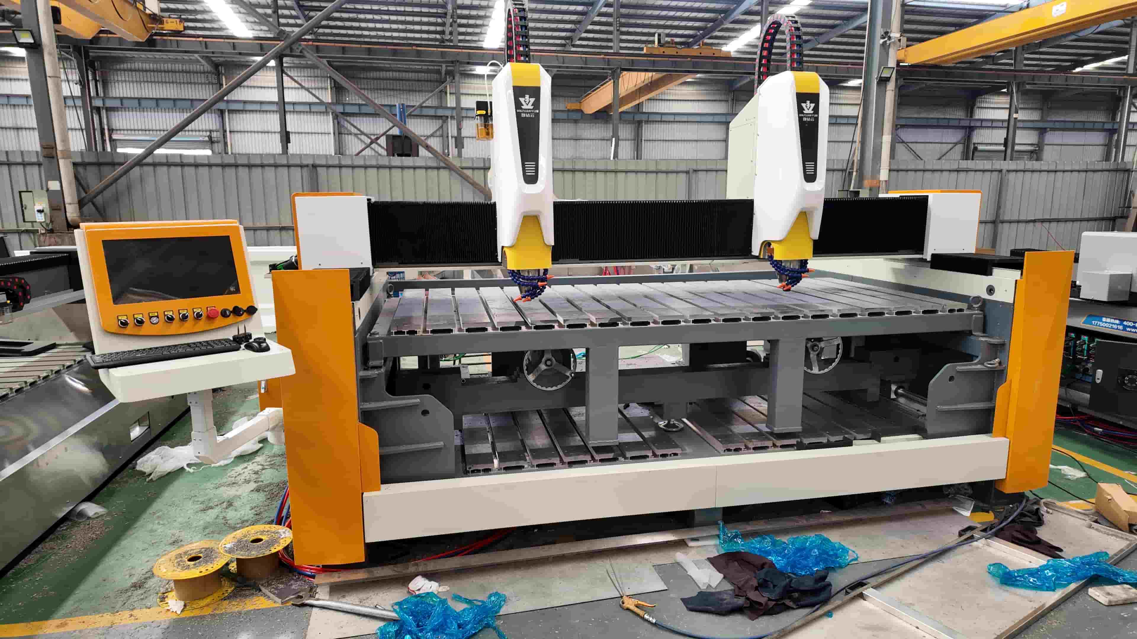
1. CNC Stone Engraving Machine (3 Axis / 4 Axis / 5 Axis)
Why It’s Essential : A CNC stone engraving machine is the core productivity machine for decorative and high-value stone processing. It replaces traditional hand carving with digital precision and repeatability.
Typical Application Scenarios:
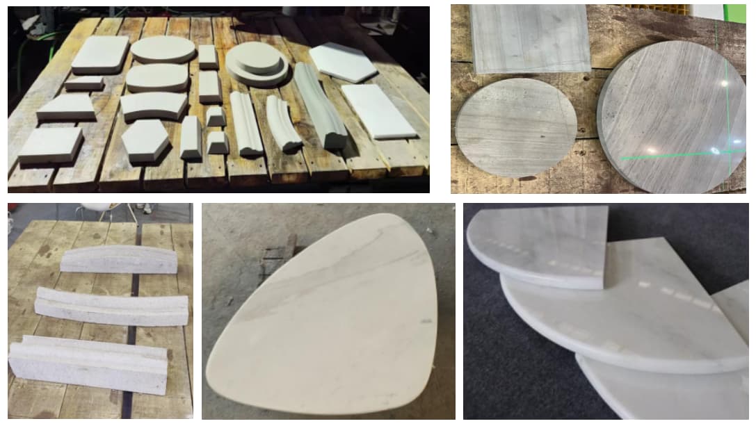
- Relief carving for tombstones and memorials
- 3D sculpture processing (statues, columns, figures)
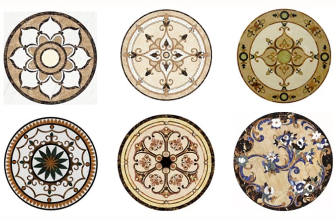
- Decorative panels for hotels, villas, and temples
- Lettering, logos, and artistic patterns on marble or granite
Technical Proof : In continuous 72-hour production environments, a high-quality CNC engraving machine can maintain ±0.01 mm positioning accuracy, even when processing hard granite with long tool paths—something manual carving cannot achieve.
Comparison: CNC Engraving vs. Hand Carving
| Item | CNC Engraving Machine | Manual Carving |
|---|---|---|
| Accuracy | ±0.01 mm (stable) | Depends on skill |
| Output Consistency | 100% repeatable | Inconsistent |
| Labor Cost | Low (1 operator) | High |
| 3D Complexity | Excellent | Limited |
| Production Speed | 3–5× faster | Slow |
Conclusion: For factories targeting export markets or premium projects, CNC engraving is no longer optional—it’s a necessity.
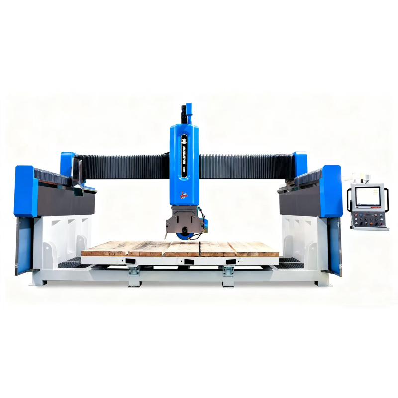
2. Bridge Cutting Machine (3 Axis or 5 Axis Bridge Saw)
Why It’s Essential: The bridge cutting machine is the foundation of slab processing, responsible for primary cutting, shaping, and sizing.
Application Scenarios
- Kitchen countertops (straight + L-shape cutting)
- Bathroom vanity tops
- Window sills and stair steps
- Sintered stone and quartz slab cutting
Key Advantage in Real Production: 5-axis bridge saw allows simultaneous cutting and chamfering, reducing secondary manual grinding by over 40% in real workshops.
Comparison: 3 Axis vs. 5 Axis Bridge Saw
| Feature | 3 Axis Bridge Saw | 5 Axis Bridge Saw |
|---|---|---|
| Straight Cutting | Excellent | Excellent |
| Bevel / Arc Cutting | Limited | Excellent |
| Countertop Sink Cut | Needs CNC | Can finish directly |
| Investment Cost | Lower | Higher |
| Automation Level | Medium | High |
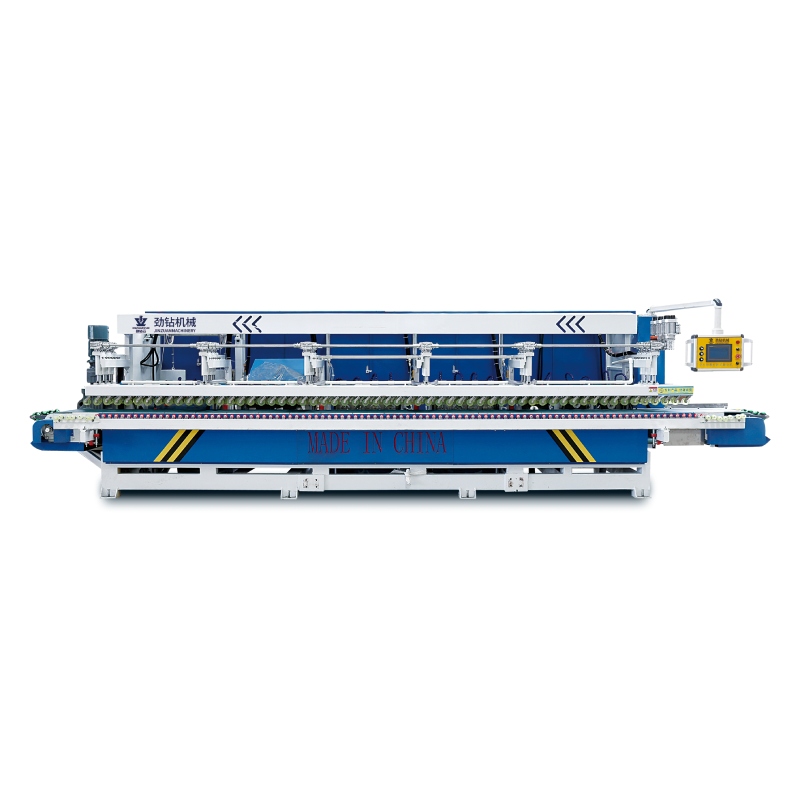
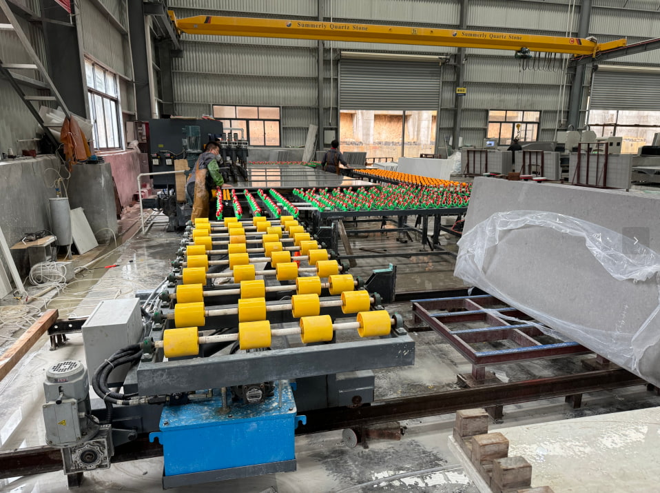
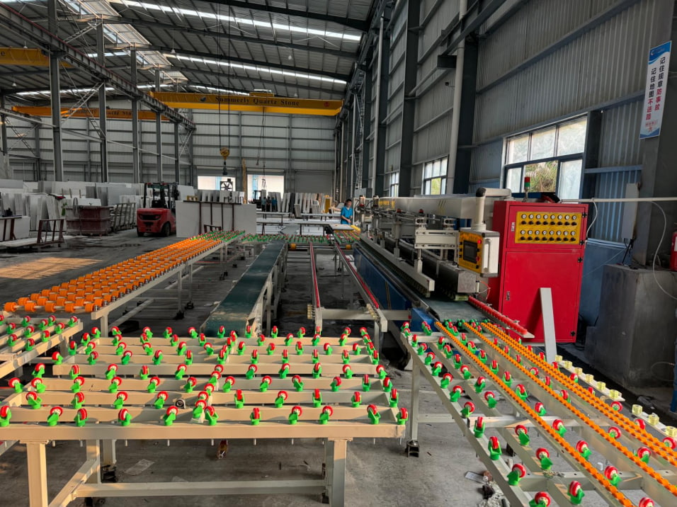
3. Stone Polishing Machine (Edge & Surface Polisher)
Why It’s Essential: Cutting defines shape, but polishing defines value. A stone polishing machine ensures consistent surface finish and edge quality.
Application Scenarios
- Countertop edge polishing (bullnose, bevel, ogee)
- Surface gloss finishing for marble and granite
- Factory-standardized polishing quality
Practical Performance Indicator: High-quality polishing lines can achieve gloss levels above 90°, even on dense granite, with tool life exceeding 15,000–20,000 meters per diamond wheel.
Common Buyer Question
Q: Why does stone lose gloss after polishing?
A: In most cases, it’s caused by unstable spindle speed, low water pressure, or inferior abrasive quality—not the stone itself.
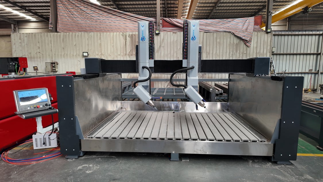
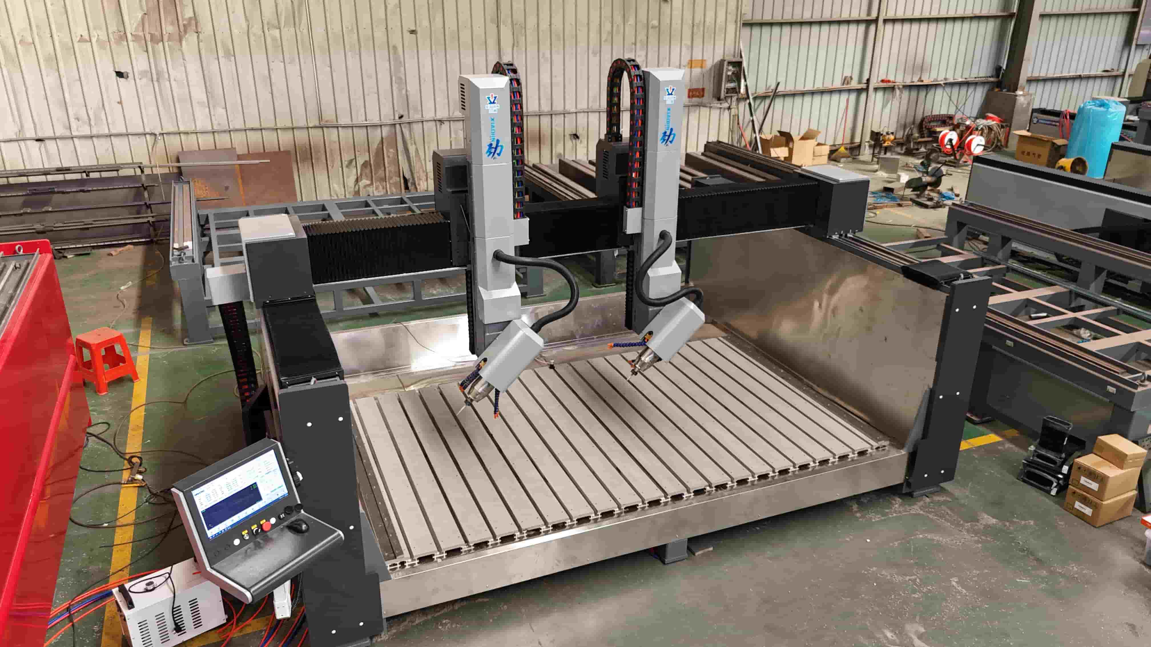
4. CNC Profiling / Copy Shaping Machine
Why It’s Essential: For repetitive shape processing, a CNC profiling machine dramatically improves efficiency.
Application Scenarios
- Curved columns and balusters
- Roman pillars and decorative profiles
- Large-volume identical stone components
Comparison: CNC Profiling vs. Manual Template Shaping
| Item | CNC Profiling | Manual Profiling |
|---|---|---|
| Output Speed | High | Low |
| Shape Consistency | Perfect | Varies |
| Operator Skill | Low requirement | High |
| Scrap Rate | Very low | Higher |
5. Stone Edge Cutting & Chamfering Machine
Why It’s Essential: Edge processing is critical for safety, aesthetics, and installation quality.
Application Scenarios
- Chamfering countertop edges
- Beveled edges for stair steps
- Anti-chipping treatment for export slabs
Performance Advantage: Compared to manual grinding, automatic edge machines reduce edge defects by over 60%, especially when processing brittle materials like sintered stone.
Frequently Asked Buyer Questions
Q1: Can one machine replace all stone processing steps?
No. Modern stone fabrication relies on machine specialization. Combining multiple machines ensures higher efficiency and better quality control.
Q2: Which machine should a startup stone factory buy first?
Start with a bridge cutting machine, then add CNC engraving or polishing equipment based on your market demand.
Q3: Are CNC stone machines difficult to operate?
Modern systems use user-friendly controllers. Most operators can be trained within 3–7 days.
Q4: How do I identify a reliable stone machine supplier?
- Real factory case studies
- Export experience
- On-site installation support
- Clear technical specifications (not vague marketing claims)
Final Thoughts: Building a Competitive Stone Fabrication Shop
A modern stone fabrication shop is not built overnight. It’s built by choosing the right machines for the right applications, supported by technical data, real processing scenarios, and proven comparisons.
By investing in these five essential machines, stone manufacturers can:
- Improve processing accuracy
- Reduce labor dependency
- Increase production capacity
- Compete in international markets


 Wide product range: Aluminum pickup truck camper, Fiberglass pickup truck camper, canopy, tent, roof car tent, RV accessories etc.
 MOQ: just 1 set.
 To receive the full catalog & dealer price list, come and send inquiries. One step ahead of time, you can seize the market first!

