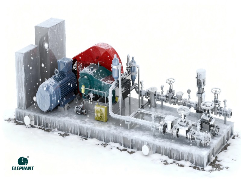
Chemical injection pumps are a type of reciprocating pump widely used in oil and gas, water treatment, chemical, and pharmaceutical industries. They enable precise, continuous, or intermittent injection of small quantities of chemical agents. Improper selection may lead to reduced efficiency, equipment failure, or even safety issues.
1. Medium Characteristics
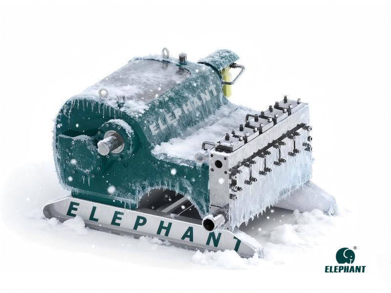
When selecting chemical injection pumps, factors such as the corrosiveness, viscosity, temperature, and solid particle content of the medium must be considered. These characteristics influence the pump's material selection, seal design, and internal structural durability. For instance, highly corrosive media require special alloys or coatings to enhance corrosion resistance. High-viscosity media demand pumps with greater delivery capacity and adaptability. Media containing solid particles necessitate attention to internal clearance design and wear resistance to prevent clogging or premature wear.
2. Chemical Compatibility
Chemical injection pumps come into direct contact with various chemical agents during operation, necessitating careful consideration of chemical compatibility issues. The composition and properties of different chemical agents vary significantly, potentially affecting the pump's materials by causing expansion, brittleness, or dissolution. If the pump material is incompatible with the chemical agent, it can shorten equipment lifespan and may lead to chemical contamination or process failure.
3. Performance Parameters
Performance parameters are a critical factor in selecting chemical injection pumps, directly determining equipment efficiency and applicability. First, it is essential to verify whether the pump's flow range meets process requirements, with flow adjustability and stability under varying conditions being paramount. Second, pressure parameters serve as core indicators. Select pump models based on actual system operating pressures to prevent pressure-related issues. Additionally, pump accuracy and repeatability are vital, particularly in scenarios requiring precise control of chemical injection volumes. Simultaneously, evaluate the equipment's operating speed, power consumption, and drive configuration according to specific requirements to ensure overall performance aligns with process demands.
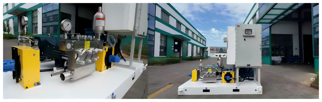
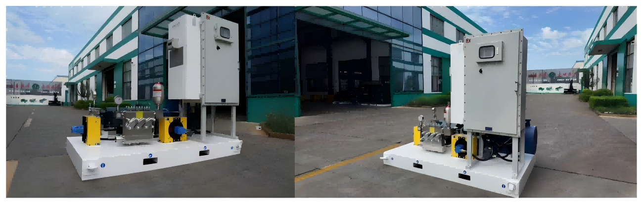
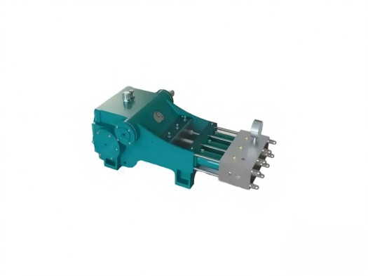
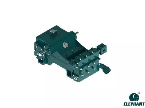
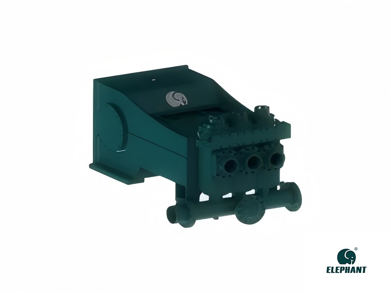
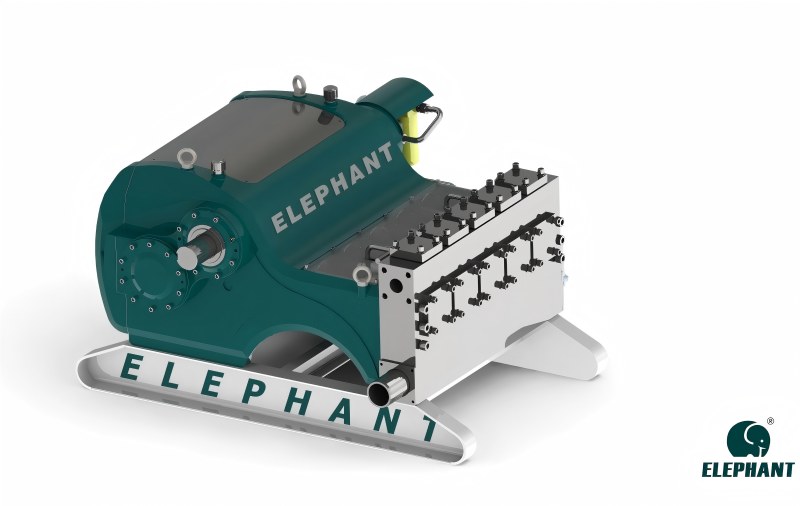
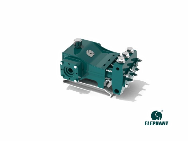
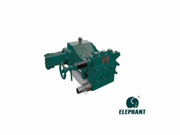
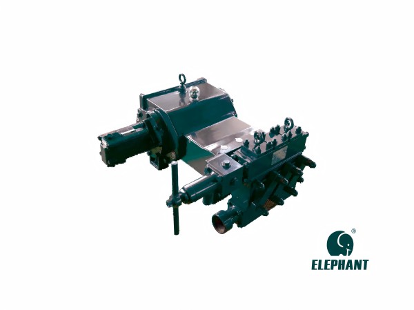
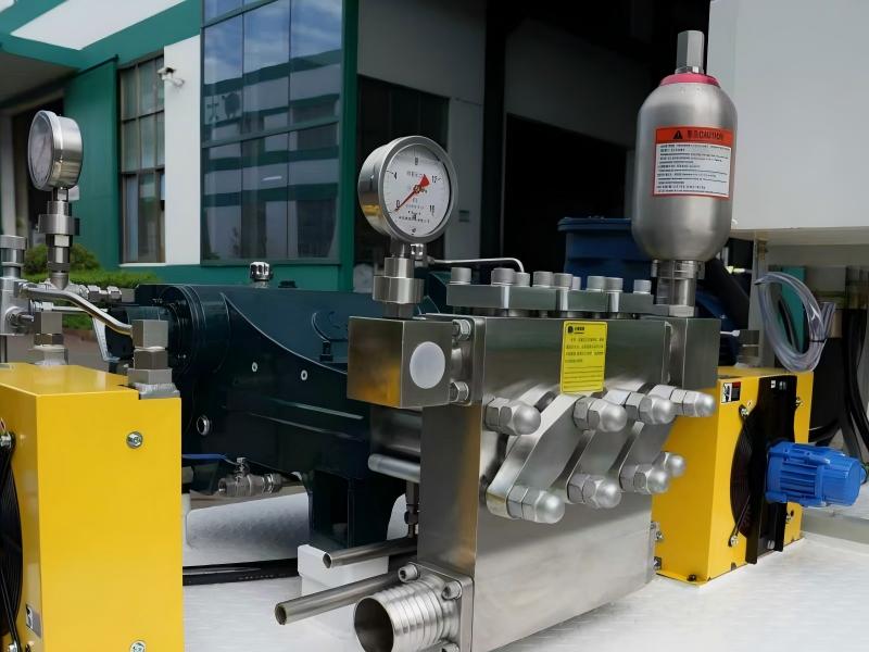
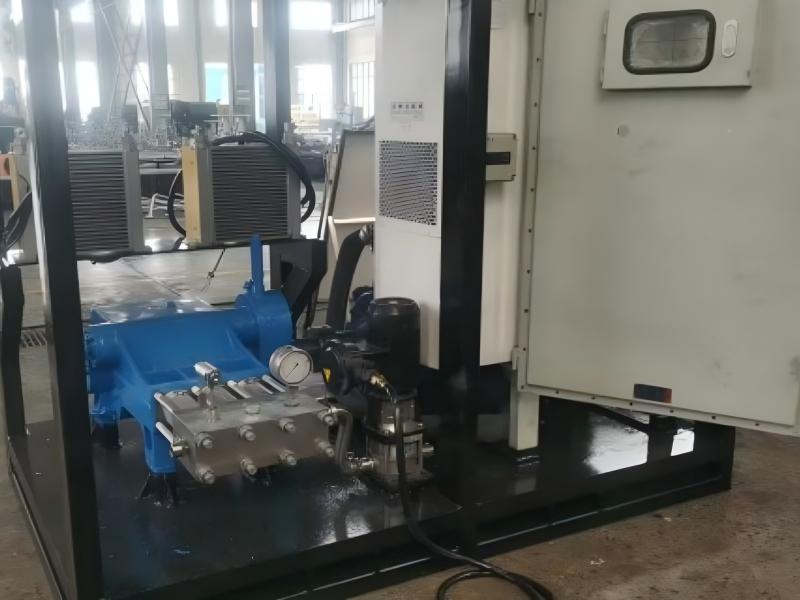
4. Pump Head Types
The selection of pump head type is critical to the performance and service life of chemical injection pumps. Different pump head types exhibit significant variations in material composition, structural design, and sealing methods, which determine the pump's adaptability to specific media and operating conditions. Furthermore, the internal flow path design within the pump head influences the flow characteristics of the medium. For media containing solid particles or high viscosity, selecting an appropriate flow path geometry can reduce the risk of clogging and wear.
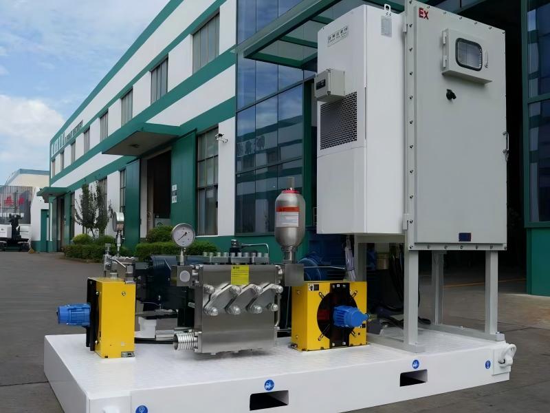
5. Safety Performance
The safety performance of chemical injection pumps is critical to ensuring stable equipment operation and personnel safety. When selecting pumps, focus on whether the design complies with safety standards and incorporates necessary protective features. Additionally, the pump's electrical components must meet explosion-proof requirements, which is particularly important when operating in flammable or explosive environments.
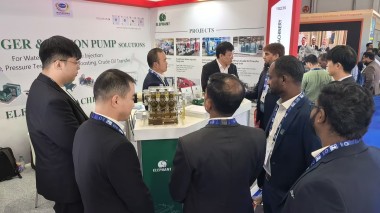
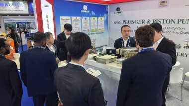
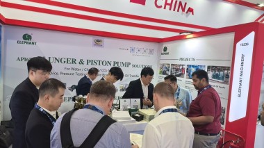
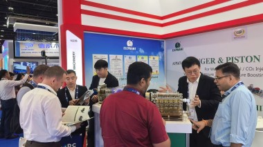
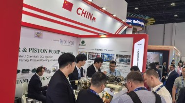
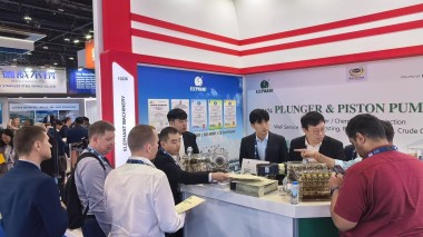
When selecting chemical injection pumps, in addition to the factors mentioned above, other considerations must also be taken into account. For instance, whether the installation space for the equipment is limited may influence the choice of pump dimensions and structural design. Elephant Machinery remains committed to providing the most professional and reliable injection pumps to customers worldwide. Whether you require a single pump or a complete pump station, we will strive to meet your needs!