A Complete Guide for Engineers, Product Developers, and International Buyers
Manufacturers today have access to more fabrication processes than ever before. Among them, metal stamping and CNC machining are two of the most widely used methods for producing precision metal components across the electronics, automotive, lighting, telecommunications, and industrial sectors.
However, choosing the right process is not always straightforward. Each method has its strengths, limitations, and ideal application scenarios. Selecting the wrong process can lead to unnecessary costs, long lead times, quality issues, or performance failures.
This guide explains the key differences between metal stamping and CNC machining and helps you determine which process is best for your part — based on geometry, volume, tolerance, material, and cost requirements.
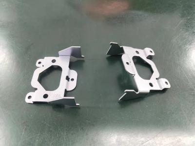
1. What Is Metal Stamping?
We won't go into detail about what metal stamping is here; we can find more information in our previous articles (Manufacturing Metal Stamping). We know that metal stamping processes transform metal sheets into precision parts through the following operations:
-
Blanking
-
Punching
-
Bending
-
Deep drawing
-
Coining
-
Embossing

Metal stamping is ideal for high-volume production, especially when parts require consistent shapes, thin profiles, and repetitive geometries.
2.What Is CNC Machining?
CNC machining uses computer-controlled cutting tools to remove material from a solid block (metal bar, billet, or plate). Popular CNC processes include:
CNC milling
CNC turning
Drilling
Tapping
Unlike stamping, machining is a subtractive process. It excels at producing complex 3D shapes, precision holes, thick components, or parts requiring multiple surface angles and depths.
Common applications:
Precision housings
Fixtures and tooling components
Automotive or aerospace parts
Low-volume prototypes
Custom industrial components
CNC machining offers unmatched flexibility since no dedicated stamping dies are needed.
3.Cost Comparison: Stamping vs CNC Machining
Metal Stamping
High initial tooling cost (depending on geometry)
Very low cost per piece after tooling
Best for: medium to high-volume production
CNC Machining
No tooling cost
Higher cost per piece, especially for complex geometry
Best for: prototypes or low-volume production
If your order volume exceeds 10,000–20,000 pieces annually, stamping is usually the more economical choice.
4.Precision & Tolerance: What Engineers Should Know
Tolerance capability is often a deciding factor in choosing a manufacturing process.
Metal Stamping Tolerance
Typical tolerances: ±0.02–0.05 mm (depending on geometry & material)
Best for thin, flat, or formed sheet metal structures
Excellent repeatability in mass production
CNC Machining Tolerance
Typical tolerances: ±0.005–0.02 mm
Capable of extremely precise dimensional control
Better for thick, structural, or multi-axis parts
If your design requires extremely tight tolerance across multiple planes, machining is likely the better fit.
5.Material Considerations
Both processes support a wide range of materials:
Metal Stamping Compatible Materials
Stainless steel (SS301, SS304, SS316)
Carbon steel
Copper & copper alloys (C1100, C2680, phosphor bronze)
Aluminum
Nickel alloys
Stamping requires materials with good ductility to ensure clean punching and forming.
CNC Machining Compatible Materials
All metals above
Harder alloys (tool steel, titanium, etc.)
Plastics (POM, nylon, acrylic)
Because machining removes material rather than forming it, material ductility is less critical.
6.Part Geometry: The Most Important Factor
Metal stamping is ideal for:
Flat, thin, or shallow 3D parts
Parts with repetitive geometric patterns (holes, tabs, bends)
Components under 3 mm thickness
High-volume parts needing consistent repeatability
CNC machining is ideal for:
Thick or solid 3D components
Complex internal cavities
Deep holes or threads
Multi-angle, multi-surface requirements
Low-volume or prototype builds
Rule of thumb:
If the part starts as sheet metal and maintains uniform thickness, choose stamping.
If the part requires material removal and multi-directional shaping, choose CNC.
7.Production Speed & Lead Time
Metal Stamping Lead Time
Tooling: 2–5 weeks (depending on complexity)
Production: extremely fast, ideal for millions of parts
Best for stable, long-term production
CNC Machining Lead Time
No tooling needed
Production time depends on cycle time per part
Suitable for urgent or small batch orders
8.Quality Consistency & Scalability
Stamping
✔ Excellent consistency
✔ Ideal for automated production
✔ Minimal dimensional variation
✔ Cost decreases as volume increases
Machining
✔ Excellent precision
✔ Flexibility for design changes
✘ Higher variation between batches
✘ Cost remains relatively high even at scale
9.Environmental & Waste Considerations
Metal Stamping
Produces scrap from punching
Scrap material can be recycled
Energy efficient due to high-speed presses
CNC Machining
Higher material waste due to cutting
Chip recycling requires additional processes
Longer machining time = more energy consumption
Stamping is generally more sustainable for high-volume production.
10.Which Process Should You Choose?
Below is a simplified decision guide:
Requirement
|
Best Process
|
High-volume production
|
Metal Stamping
|
Low-volume / prototypes
|
CNC Machining
|
Lowest cost per part
|
Metal Stamping
|
No tooling budget
|
CNC Machining
|
Ultra-tight tolerances
|
CNC Machining
|
Thin sheet metal parts
|
Metal Stamping
|
Complex 3D geometry
|
CNC Machining
|
Fast mass production
|
Metal Stamping
|
* In many real projects, both processes are combined, for example, stamping the outer geometry and machining critical features.
11.Why Many Overseas Buyers Choose Metal Stamping Partners in China
International customers often choose Chinese metal stamping suppliers because of:
Mature tooling & die-making ecosystem
Competitive cost structure
Skilled workforce and automated equipment
Stable raw material availability
Ability to scale from prototype to mass production
For example, manufacturers like Jiaxin (Xiamen) Precise Metal Co., Ltd. support customers with:
23+ years stamping experience
1000 & 10,000 class cleanroom production
In-house tooling and engineering team
ISO-certified quality control
High-precision presses and inspection equipment
Custom OEM/ODM support for global clients
 Precise Metal Co., Ltd.")
Both metal stamping and CNC machining are powerful and reliable manufacturing processes. The right choice depends on your part’s geometry, tolerance, material, budget, and production volume.
If you need high-volume, thin, and repeatable metal parts, stamping is almost always the better choice.
If your parts require complex 3D geometry or extremely tight tolerances, CNC machining is more suitable.
A professional supplier can help evaluate your drawings, material selection, tolerance requirements, and cost targets to recommend the optimal process or a combination of both.
Related articles here:
Manufacturing Metal Stamping
Benefits of Custom Metal Stamping Parts for Automotive, Lighting, and Household Appliances
How Precision Stamping Helps Reduce Production Costs and Improve Efficiency